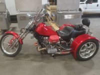
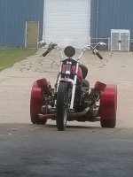
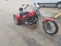
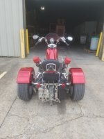
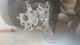
Anyone else?

I got a couple hours this evening and worked on the electrical. I had made up a bunch of the harnessing a while back and it has never been powered up.

So now the "body" side is is sorted out now. I will not have many niceties but after some tinkering all the requirements work. It was a but worrisome as I have switched everything to npn (negative switching) and on relays.

Next is powering up the computer and all the engine controls.
 
??????

I see the ox sensor bungs in the headers. So, will this be a wideband controlled setup, or will you have to map both ign. and fuel?? I'm not real up on this stuff , but reading up, and interested. I have been working with the stock chry 2.2 turbo t1 setup,getting some problems solved. Starting to understand it somewhat. I understand the challenge you have taken on! Good luck with it.
 
Yes I will have to write the maps.

It is narrow band right now. It may become a wide band if I can not tune it like I want.

It will have a map for 1 and 3 and a seperate map for 3 and 4. Just like the headers are split.

And it is split like it is for this reason. It is the synchronized pairing and will tune the best.

Then there is a map for the ignition also.
 
Ok.....so the "body" side of the electrics is up and working. Had to sort a few pins in the connectors but nothing drastic. All the npn (negative switched) on relays worked out.

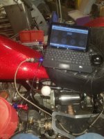
Booted the computer today.

Still sorting stuff out there.

The temperature inputs all seemed to work and calibrate fine.

The tps has a real short span and is twitchy as all get out.

Have not gotten to the O2 inputs yet.

The outputs seem ok so far, not much is plugged in on the output side right now.

20170501_185415_zpsjf6pfyiv.jpg
 
Well.....

The twitchy tps was my fault.

Had the 5v and vref backwards.

Opened up a solder joint and swapped the two eires and all good. Then soldered and shrink wrapped them back up.

Got a good ref, span, and smooth ramp on the tps now.

One more thing settled. The joys of mixing and matching different brands of electrical parts. Everything works on the same principles but wiring can be a bit different.

20170503_174847_zps8ypur1cc.jpg
 
more ????

Don't see any intake crossover?? Are you using separate mass air flows sensors or 2 map sensors or one common map?? Also these npn relays you speak of.... do you mean they are solid state relays npn type, or common relays using npn transistors to drive the relay coil? I have read the entire build but, maybe missed/forgot some stuff along the way. Thanks.....
 
I am not sure what you mean by cross overs.

But it is independent throttle bodies. Like a motorcycle. Four completly seperate throats.

I doubt I will have enough vacuum to use a mass air pressure set up. I do have a map soldered on the cpu board and I may get some useful info from it.

But I plan on being alpha n. The calculations based off the throttle position sensor.
 
And yes the relays are std stuff. It is the controll logic that is npn.

I hid the wiring inside the handle bars. All of it is on the negative side and small in size. If something were to short out in the bars all it would do is turn something on.
 
more ??? but starting to understand

... by the term crossover, i maybe should have said, balance tube? ( connecting one intake bank to the other side) however you are using throttle bodies. i had also wondered, if there was a mass airflow sensor, or a manifold pressure sensor for each side. or each throttle body....if it is a speed/density system? ie. map sensor/rpm/throttle position and engine temp inputs. If i understand you correctly, throttle position/ rpm are your inputs?then no engine load data, (map sensor data) needed?
 
... by the term crossover, i maybe should have said, balance tube? ( connecting one intake bank to the other side) however you are using throttle bodies. i had also wondered, if there was a mass airflow sensor, or a manifold pressure sensor for each side. or each throttle body....if it is a speed/density system? ie. map sensor/rpm/throttle position and engine temp inputs. If i understand you correctly, throttle position/ rpm are your inputs?then no engine load data, (map sensor data) needed?

footnote here ....just read up on alpha n fuel systems....understanding now....my setup is speed density...some are speed density at lowpower/cruise and alpha n for top end.... this alpha n should work for you! going to follow this thread closely!!
 
Yes I have all those inputs except for a mass air flow. I have open air filters and no ducting for an air flow meter to be.

Even though I have a MAP sensor I doubt that I have the vacuum to work it. If I did it would be the better "load sensing" input and make the best table for general purposes.

So if you are looking into setting up fuel injection, I would recommend speed density and a map sensor. As long as you are not running a huge cam and independent throttle bodies at the same time. A milder cam and vacuum hose from each throat going to a plenum can with yhe map hooked to the can would work just fine. Or a plenum intake and a single throttle body would be the easiest to set up.
 
Well.....when I get a day off it is usually Saturday.

But no scooter work this time.

Was at the school waiting on my girlie taking the ACT's

Friday after work I did get the o2 sensors hooked up. Did power up, but have not tryed to calibrate.

Started plugging in outputs. The injectors click like they work. The ford ignition has a problem. No time to troubleshoot, but probably a wiring error mixing these parts.
 
I have been back through all the wiring. Even had the computer all apart and ran it on fabricated inputs. Everything still checks out correct.

Screenshot_20170607-202644_zpsmp17doft.jpg

So the only thing left is the Ford module has to be bad. It did come from the junk yard and dont know it it was good/running when it went there.

_1%202_zpsjfsegeys.jpg

Now to get a new one of those......or do something else entirely. The only big reason this type was choosen was simplicity. It is external of the original cars computer and has the coil drivers and all the dwell all built into it. I could do it a more modern way and build those parts into my computer.
 
have read some recently on edis. supposedly it can run stand alone with 10 deg. adv, or with SAW?? input, it can have an advance map with microsquirt inputs. maybe your setup is different. just trying to understand, but not much help! good luck on the trouble shooting!
 
Yes.

It is sort of stand alone. More modern cars have the parts that are in that seperate module built inside the engine computer.

Yes it will wire up and run with no advance without a computer.

It outputs a pip (profile ignition pulse) which is a pulse like you think of a tach.

And you input a saw (spark advance word) to tell it how much to advance.

It is an old set up from the 90's, but it is simple.

A more modern approach would be coil on plug or the ever popular chevy coil near plug.

Maybe one day I will upgrade the conroller to full sequential and coil on plug
 
dumb question

Yes.

It is sort of stand alone. More modern cars have the parts that are in that seperate module built inside the engine computer.

Yes it will wire up and run with no advance without a computer.

It outputs a pip (profile ignition pulse) which is a pulse like you think of a tach.

And you input a saw (spark advance word) to tell it how much to advance.

It is an old set up from the 90's, but it is simple.

A more modern approach would be coil on plug or the ever popular chevy coil near plug.

Maybe one day I will upgrade the conroller to full sequential and coil on plug

Does your trigger wheel have 36 teeth with 1 missing to identify tdc ? Is your ckp air gap correct? I've had 0.010" make a difference
 
Yes I have all that.

The pip signal from the edis module seems to be bad. It is reporting 80,000 rpm. Which I assume is the limit of the software.

Disconnected from the computer and with a fake pip input signal everything test good, even the saw signal.
 
It has been a while.....

So busy with everything else in life.

I still have to trouble shoot the ford ignition parts.

Building a test rig for it so I can actively run the ignition without an engine.

So no real news, just have not messed with it for about a month.
 

Welcome to the Trike Talk Community

Join our vibrant online community dedicated to all things Trikes! Whether you're a seasoned rider or just starting out, this is the place to share experiences, tips, and stories about your three-wheeled adventures. Explore modifications, maintenance advice, and rides, all while connecting with fellow trike enthusiasts from around the globe

Forum statistics

Threads
55,289
Messages
786,215
Members
22,757
Latest member
Eddienorman
Back
Top