Before I

Mar 11, 2018
489
308
Fernley, NV
Name
Andy
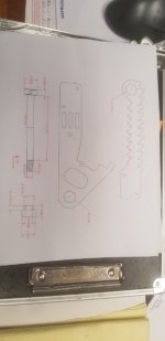
get a head of myself I thought I would post a pic and see what is said.

20180912_144630.jpg

The drawing is not perfect all the way, but it is the basic set up I came up with.

I cannot have 3/8" of head bolt sticking out that far because of the disc brake rotor. So if I remove 5/16 off the inside edge, well it leaves just over an 1/8th of inch of head bolt sticking out past the down tubes inner edge.

I also need more axle space for the caliper support arm and the rockers have to be on the outside edge of the fork tubes center line to accomplish this.

I end the shoulder bolt with a bronze washer (1/16th" thick) for the shoulder bolt, jam nut followed with the cap nut. Maybe a few shims if needed.

I can not find low profile bolt heads in 5/8" dia., half inch dia. has more choices, but I want to use 5/8" dia.
 
It does look like you are getting everything accounted for.

Leave enough room for a brake stay.

I also used 5/8 shoulder bolts. As I am rough on mine I tried to make the pivot stronger. But the eye design you are using is the most common out there and mine is the odd ball.
 
Again, Thank You for all your help.

While as I was going over things today, I discovered my mind stuck on a idea, when I opened up the mind to other things, well I am just glad I did not start anything solid yet. I will get it nailed down soon.:D
 
beautiful front end there!...one to duplicate if possible, I for sure couldn't match the workmanship, or design.

I didn't see much detail on the brake reaction rod, or it's fastening to the fork leg......mine could stand a rework, and Andy needs to build his.

Rex could you show this area more clearly?

thanks
 
The links are the same center to center as the rockers.

I know the rockers each have a different shape, but all that matters are the centers. They are dimensionally the same.

Then they are parallel to each other.

From there it is just shoulder bolts and bushings.

The fork legs are simply drilled and tapped.

I will look for pics.
 
Thanks Rex, I didn't know about the correct linkage layout when building, Rodekyll had a thread concerning this , but too late for me....as a result my front climbs to max with hard front brake, will correct this winter.....thinking Andy should get this right when he gets to this point.

thanks again
 
attachment.php


This is what I got down for the caliper support and the piece of 304SS I will use for it.

20180916_071219.jpg

A straight on look at how all sits, yes this front edge of the caliper looks to close to the rotor, but

20180916_071732.jpg

the back side is setting a little high, the pads edge is just a hair above the rotor, so mounting hole location is issue, lower the back some and the front might rise some if I do not use the center mounting bolt, once all is as needed, than mark and place the center mounting hole.

Play time and more patterns, LOL

20180916_070505.jpg

I did get the tube and tire installed on the rim yesterday, oh and properly mounted the rotor into place. So in the process the little square weight fell of the rim, yet when I did the spin test on the wheel, well it spins for some time and always just rolled to a slow fine stop, no more forward or reverse movement. Did this so many times the wife wondered what I was wrong with me, LOL

Brake lines, you can buy them ahead of time, but good chance they will need to be returned as they are to short or to long

So one also can not forget the extension of the suspension and how much free brake line is needed. If you measure for the line as it will sit in riding position, need to add the suspension extension length to that initial measurement. I am looking at 62" of brake line and I do wonder if two short lines would work better.

One from hand M/C ran down handle bars and part way down the forks to a transfer block. The second line would go to the caliper and contain the extra extension length needed. I see this as a way to help guide how the brake line will lay and extend and retract with the suspension and keep it out of the way of things. Just moving along.
 
Hope all are having a good week, I lost a day aready, LOL

So I got the correct thread and length bolts for mounting the caliper to the support bracket.

I played with travel motion and all that to make sure that the pads will ride the rotor all the time.

So the final pattern was crafted today with precise bolt holes and axle hole location. I got excited because it was done and worked out, now to put it on the steel and get it cut and shaped.

Waiting for more quote feed back on the fork tube work. Just poking along getting things done.

Rex, that is such a tight fitting front end. I know it was to help me get over my clearance issue, wow, very tight, but I see it can be that way and work. I just kept thinking of the rotor scrapping bolt heads and wondered about a front flat tire and etc., just feel better if I have more clearance than you, wont be much, but a little bit more I hope.

Have a good evening everyone.
 
I paid the price. Thought I would order the metal I needed online, that I did, but maybe not the best idea.

Well the truth is, I do not know metal worth a ?. So I did read about using cold rolled steel over hot rolled, and it is highly advised against hot rolled steel.

It is hard stuff. Some how I got a piece of hot rolled over the cold rolled I ordered. I did not know the difference in looks of the two metals, so figured I got what I wanted, plus a custom cut size, NO returns on custom cuts.

It took me over 3 hours yesterday to cut 3" of length, jig saw and metal blade is not the best method on 3/8" thick SS.

Will try the cutting wheel today and see that goes. Oh yeah, pay attention to undercut sizes listed, seems they favor to give you the undercut length than what you want, at least on me, so order a 1/4" larger in size or more as it depends on their tolerances on cutting sizes. Live and learn, this is a hard lesson to forget, as it is much harder working with this material.:(
 
There is a difference in hot rolled steel and cold rolled steel.

But you are not working with steel are you?

You are working with stainless. There is little to no mechanical difference between cold 2b finish 304 ss, and hot mill finish 304 ss. It is not the same thing as carbon steel definitions.

Most any stainless over 3/16 thick will be mill finish.

Stainless (even though not much different than steel structurally) does machine very differently.

So cut speed, drill speed, turning/milling, will all be at roughly half the speed. Or in other word....take double the time and power to do.

So when you are ready to drill a hole.....half the rpm.....double the pressure.....and it will take twice as long.

And yes thin abrasive cut off wheels work well.
 
That is it, the thin abrasive cut off wheel works wonders, operator just needs a steady hand, LOL

I did not do a super bad job, just a little extra grind time to get to pattern line.

I got this far yesterday, just the top curvy line to cut out today.

20180922_202635.jpg

I could only fine 50 grit sanding drums locally, they take some time, but they do work on cleaning up the edges.

20180922_202607.jpg

I just wanted a support bracket, but the daughter seen it laying around and had to put her touch to it, children...….

20180922_202655.jpg

pic did not stay rotated, but I guess it looks like the "hang loose" sign

Well I did not get to read all that Rex, thank you for educating me about the metal.

So I have some work time ahead of me, fun, but nothing good ever comes easy. Better tools, maybe time to get that nice belt sander. It really would help with this project and I really wanted one for my flute making. Tool shopping time.
 
There is a difference in hot rolled steel and cold rolled steel.

But you are not working with steel are you?

You are working with stainless. There is little to no mechanical difference between cold 2b finish 304 ss, and hot mill finish 304 ss. It is not the same thing as carbon steel definitions.

Most any stainless over 3/16 thick will be mill finish.

Stainless (even though not much different than steel structurally) does machine very differently.

So cut speed, drill speed, turning/milling, will all be at roughly half the speed. Or in other word....take double the time and power to do.

So when you are ready to drill a hole.....half the rpm.....double the pressure.....and it will take twice as long.

And yes thin abrasive cut off wheels work well.

Not my cup of tea, just know enough to be dangerous, so any tips and tricks I should be aware of Rex ??

I used a carbide jig saw blade to cut the short side with, the thin cutoff wheel for the longer side, guess I will give a new 24tooth blade the test for this curvy edge.

Any drill bit tips, special type that will work better than standard, or does it matter, or should I let a machine shop punch my holes for me ??

Any help is welcomed, seriously I do not know as much as I should know for this project, now just need to finish it.
 
can't offer much but encouragement at this point....never dealt with stainless at work....just mild steel and air hardening tool steel.

by accident bought .040 x 4.5 in. cutoff wheels instead of the .060....what a difference....the saws are covered with dust!:D
 
I zipped through the straight lines, so all rough cutting is done. Between the jig saw and the cut off wheel I am keeping close to the pattern line so far. Get so far into the curve than use the cut off wheel to remove material, and than the jig saw is back at work. Not sure how much I will get done today as so many other things on the "To Do" list.
 
Just mostly what I said above.

Those silver colored drill bits from the hardware store are ok for wood.....but little else.

Black oxide bits work ok....slow

Cobalt holds up... but is brittle and easy to break.

Real carbide is way way brittle and can not use by hand at all.

Use cutting oil and/or keep it cool. Cutting tools will burn up melt real easily in ss.

I use Castrol moly dee for low speed cutting lube.

Castrol_98-890-7.jpg
 
Like most think a drill bit is a drill bit, but we have wood bit for soft, medium, and hard wood, duh...…. guess you would have the same for the different metals out there.

I had the cutting oil and no way was I going to get any cutting down with out the oil, and as you said slow and steady seemed to get me done faster than running the saw at higher speeds.

It just takes a lot of time and pressure against the sanding wheel to work the edges to the fine pattern line, really only have one major area that has to be dead on the pattern line, that top curvy line and that will take some time to get done.

Thank you all so much for all the help and advice, as we are getting closer to getting this done.
 
almost done, help need advice

Okay spent the last few days drilling holes in the 304 SS 3/8" thick plate. I read you and seen on you tube that you should drill pilot holes first. 1/8" inch is what was used the most, than step up, so the 6mm only had to do the next size up, the two 8mm bolts to an extra pass. Basically went in 3/32nd increments.

Used what local store had, thankful it was the recommended type drill bits.

20180928_154153.jpg

20180928_153420.jpg

Now all needs to mount up correctly.

20180928_153924.jpg

Okay I got a little lucky that I got all drilled on the mark, no margin for error in how I went about it.

Now please note: You want to figure out the most important hole first, get it right, than any others in order of importance. A lot of work just to get the pattern cut out and shaped, all could have gotten screwed up if I drilled wrong.

Now please help me, look at the bottom 1/8th inch pilot hole drilled at the axle location, got it on the money also, but this is the hole I should have drilled first actually and now I doing it last.

So 7/32, 5/16, 9/16, and than the 3/4" bit ?? or can one do the 1/8, 5/16/,9/16, than3/4, or 5/16 and than 3/4 ?

Okay next big question. Axle is 17mm dia. and if I drill a 3/4" hole and use the bronze pushing, well it's internal dia. is 5/8" and so it would need to be reamed out to the 17mm, I think that would be to thin.

Catalog has a 26mm outer dia. with the 17mm internal dia., and 26mm is near a inch. I guess I will look more later for bushings. Help me if you can please.:)
 
maybe try for a bushing size that gives approximatly an 1/8 in. wall thickness........there should be metric bushings w/17mm id x 25mm....then drill/ream a hole in your mount like 7/8 then have bushing turned on the o.d. to fit the drilled/reamed hole with a light press fit ......just a suggestion?
 
I will look, but if all I can get is the 17x26mm O.D. bushing, than Bamm, still in business. As you said just have the outside turned down to fit what I need.

So if I want 1/8inch thick bushing, than I should do a 13/16 inch hole, might have to do 7/8" because of what drill bit is available to me, but I got your point Larry.

Any ideas about drilling the hole, do you really need to slowly increase the drill bit size until you get to the size you want ?
 
Step drilling helps. Step up however whatever drills you have.

But the last step before finish should be barely less than finish size.

The lighter the cut and the sharper the finish drill is, the more accurate the final size.

So....twist drills typically are only good to +.005 tolerance.

In a machine shop you would step drill it up to .015 under size and then put a reamer through it.
 
I was never told about it that way. If I get the larger tolerance in bushing size than a 3/4 hole will be undersized a little.

The brake support bracket is the hard one, not lot of room and all the bushings have large OD to them, so I will just get the bushing turned down to press fit into the bracket.

Enough work for the day.
 
The bushing that is located in the caliper support bracket which rides on the 17mm axle.

Now I had planed on just drilling a 3/4" hole like on the rockers, but I see the rockers will need to be larger at 7/8" dia for the axle hole so I can use that larger bushings so I can ream it out a bit for the 17mm internal dia.

*** the question is how much bushing is truly needed on the support bracket ?

the 3/4" OD x 5/8 ID bushing will give me 2mm of thickness of material after I ream inside to 17mm dia.

This is close to 3 / 32 of inch thick bushing, shouldn't this be enough for the support bracket to roll on the axle ???
 
If I am understanding correctly...your axle will be fixed, the only rotation will be the caliper mount itself, and it will be only a few degrees when the brakes are applied. A bushing wall of 3/32 would be fine , The main reason for the bushing is to avoid the undesirable situation of having steel on steel. Hoping I'm on the right track here?
 
Going back and looking at the numbers......it look like my bushings are .125 wall

The main reason is that they are off the shelf items from any industrial hardware supplier. MSC, Granger, McMaster carr, ect.

20180929_195811.jpg
 

Attachments

  • 15382312803350.jpg
    15382312803350.jpg
    47.4 KB · Views: 134
Also.....you keep saying "on the axle".

I am not sure what you mean there.

The axle for the wheel itself will not have any bushings on it.

The brake stay will be on a bushing that rides on the axle spacer.

I suppose you could make up the bushing as a replacement for spacer length. That way the stay would rotate on a fixed bushing. But I would not want brass as a spacer. Would prefer the axle be more solid tight.

Attempt a pic. But it is hard to tell the stay is on the od of axle spacer.

15382313309964.jpg
 
I barely can see it, but I do see what you are talking about. I got it wrong from the start than as I thought it just road on the axle and that is why it needed a bushing in it, so the bushing wore not the axle or bracket.

This rim, rotor, and factory spacer out of the hub allows the support bracket to mount flush up against the hub spacer, this is in alignment with the rotor for caliper mounting.

I take it a thin friction shim should be between the hub spacer and the bracket, spacer is aluminum and bracket is 304SS.

I see if one long spacer was used, to cover distance between rocker and factory hub spacer, and if is press fit onto the spacer at the end, that would work, but my mind says I still should use a friction shim between things.

Oh, my mind is gone, a 3/4 OD and 5/8 ID, does not mean a 1/8 inch thick bushing, it is only 1/16th of inch thick on each side, duh...…………

So is that right size to use on the 5/8" shoulder bolts on the rocker arms ? or do we want the bushing to be 1/8th inch thick wall ??

If I got this wrong I have to change things up and go to 7/8" OD on the hole with the 5/8" ID, guess would not be bad as I have to do that up front for the axle hole, go 7/8" OD and have the inner reamed out to 17mm, that is if we want the thicker walled bushings.
 
got it!....no part of the axle bolt 17mm diameter is exposed. Just axle spacers....true you must pivot the caliper mount on one of the spacers. I've got a drum up front, so reaction link to the bail, which I have since learned should be to the fork tube. maybe this winter...

Getting back to Andys mounting plate

are there any provisions needed to prevent side to side movement on the caliper mount?:confused:
 
Let's get it started correctly.

The axle is 17mm dia. and is a fixed axle, meaning the rocker arm will have a set screw in it to hold the axle in a fixed position.

Rockers can collapse inward if spacers are not used, I will need spacers to keep the wheel hub centered on the axle.

side to side movement, well if brake stay was pressed on a bushing and that slides onto the axle and than the final spacer, the brake stay would be kept in it's location by the two spacers, and of course we have the reaction arm that will hold the brake stay from rotating to far.

So we use a press fit bushing on the spacer. The spacer will roll on the axle, if not, than the brake stay rolls on the bushing that is pressed to the spacer ? Or is it do to the fact that the spacers all push up against each other and this pressure keeps them from rolling around the axle ? so for this reason the brake stay must roll around freely on the press fit bushing on the spacer ?

If you press fit the bushing into the brake stay, than as the brake stay rotates a little the bushing rolls on the axle, not the steel brake stay...….that is what my mind has always seen, spacers on each side keep all in position and centered.

I say the question is which method gives the most free movement, eliminates the chance of binding...….and I think my idea or way, well is seems it could have more pinch or binding because more parts are involved.

but if you tighten up the axle bolt to much than spacers bind up on each other and my way is not freely moving.

I see if brake stay was riding the bushing on the spacer, well brake stay will still rotate on the bushing that is fixed to the spacer.

So if this is the case, I will need to drill a much larger hole for the large bushing.

17mm dia. axle, 19mm = 3/4", so that is a 1mm wall thick bushing.

So a 1" OD bushing with a 3/4 ID pressed onto a spacer that is 3/4" OD with a 17mm ID, but the spacer has to be fixed so that the movement of parts are on the bushing and not spacer to axle area ?
 

Similar threads

Welcome to the Trike Talk Community

Join our vibrant online community dedicated to all things Trikes! Whether you're a seasoned rider or just starting out, this is the place to share experiences, tips, and stories about your three-wheeled adventures. Explore modifications, maintenance advice, and rides, all while connecting with fellow trike enthusiasts from around the globe

Forum statistics

Threads
55,524
Messages
806,701
Members
24,071
Latest member
ledgin
Back
Top Bottom